Order your End-Fed Half-Wave Antenna 80m Extension Kit!
Download the pdf instructions HERE
Winding the Coil
The completed coil should have an inductance of ~ 110 ?H. This is achieved by winding 170 turns of the included 0.5mm magnet wire around the included PVC core.
In order to center the coil on the PVC core, drill a hole 1 1/8 inches or 29 mm from one end using a drill size of at least 3/64 inch, or 1mm.
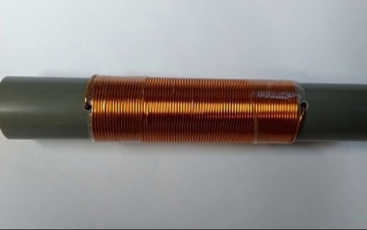
Pass one end of the magnet wire through the hole, leaving sufficient wire (approximately two inches or 50 mm) outside of the PVC core for soldering in a later step. Starting from the hole, wrap 170 turns around the PVC. Keep turns wound tightly against each other. The final width of the properly wound coil on the PVC core should be about 3 7/8 inches (98 mm).
After “locking” the coil in place with tape, drill another hole, in line with the first hole, as close as possible to the finished coil. Pass the end of the magnet wire through this hole and out the other end of the PVC. Leave approximately 2 inches (50mm) of wire outside the coil to comfortably solder to the extension wire. The finished coil should look similar to the image below.
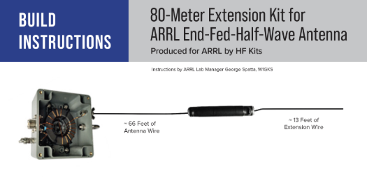
EFHW 40 – 10 m Radiating Wire
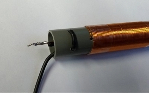
To attach the ~ 66 foot radiator to one side of the coil, two holes at least 13/64 inch or 5.5 mm in diameter need to be drilled about 1/2 inch or 13mm from one end of the PVC, and these holes should be spaced roughly 3/4 inch or 20mm apart. See the image below.
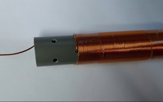
Run the end of the radiating wire through the two holes as shown in the image below. Roughly 2 inches or 50 mm from the end of the wire, tie a knot and pull the wire back through the core until the knot is pressing against the inside of the PVC. The extra wire will be soldered to the magnet wire.
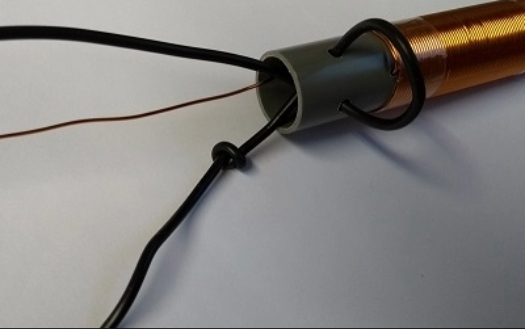
Trim both the magnet wire and radiating wires to a comfortable length. Making sure the enamel on the magnet wire is properly scraped back where it will be soldered. See the image below.
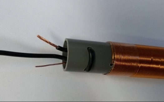
Twist the two wires together and solder as shown in the image below.
80 m Extension Wire
To attach the 80 m extension to the other side of the coil repeat the steps above shown in Figures B through E on the other end of the PVC.
With the coil fully assembled to the antenna you can now move on to tuning the 80 m extension and carefully trimming the extension wire for the lowest VSWR on the band segment of interest. The end of the wire can be folded over on itself and secured with tape while determining the needed length before actually trimming the wire. Tuning the length of the extension wire should be done at the intended deployed height. Having to raise and lower the antenna several times to fine tune the extension wire is a normal part of the process. VSWR on all bands (80 through 10 m) should be checked before trimming the wire.
If installing the 80 m extension to a previously built EFHW antenna with the ~ 66 foot radiating wire trimmed for 40 through 10 m operation, you may see a shift in the resonant points on those upper bands after installing the 80 m extension kit. Using an antenna tuner, which is recommended for 80 m use, should compensate for any shifts on the upper bands.
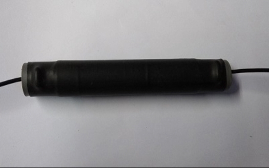
When you have completed tuning and trimming the wires, install the included heat shrink tubing over the coil as shown below in the image.
Publications & Online Store >> Product Notes >> EFHW Antenna 80m Extension Kit


